
01→
CNC plasma
Cutting of plate up to 80 mm thick with ±0.5 mm accuracy.
2 units
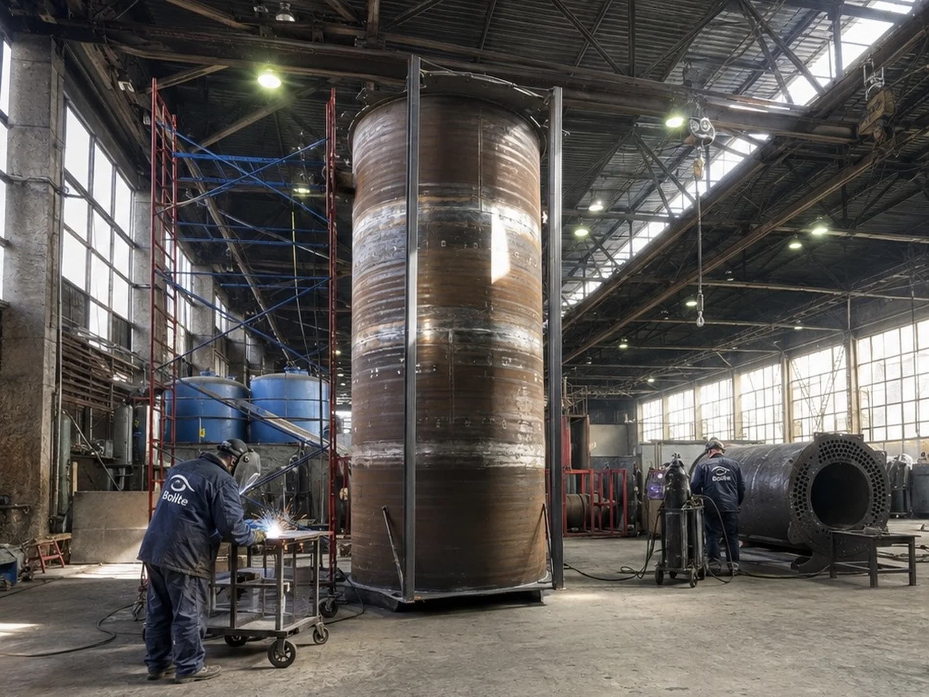
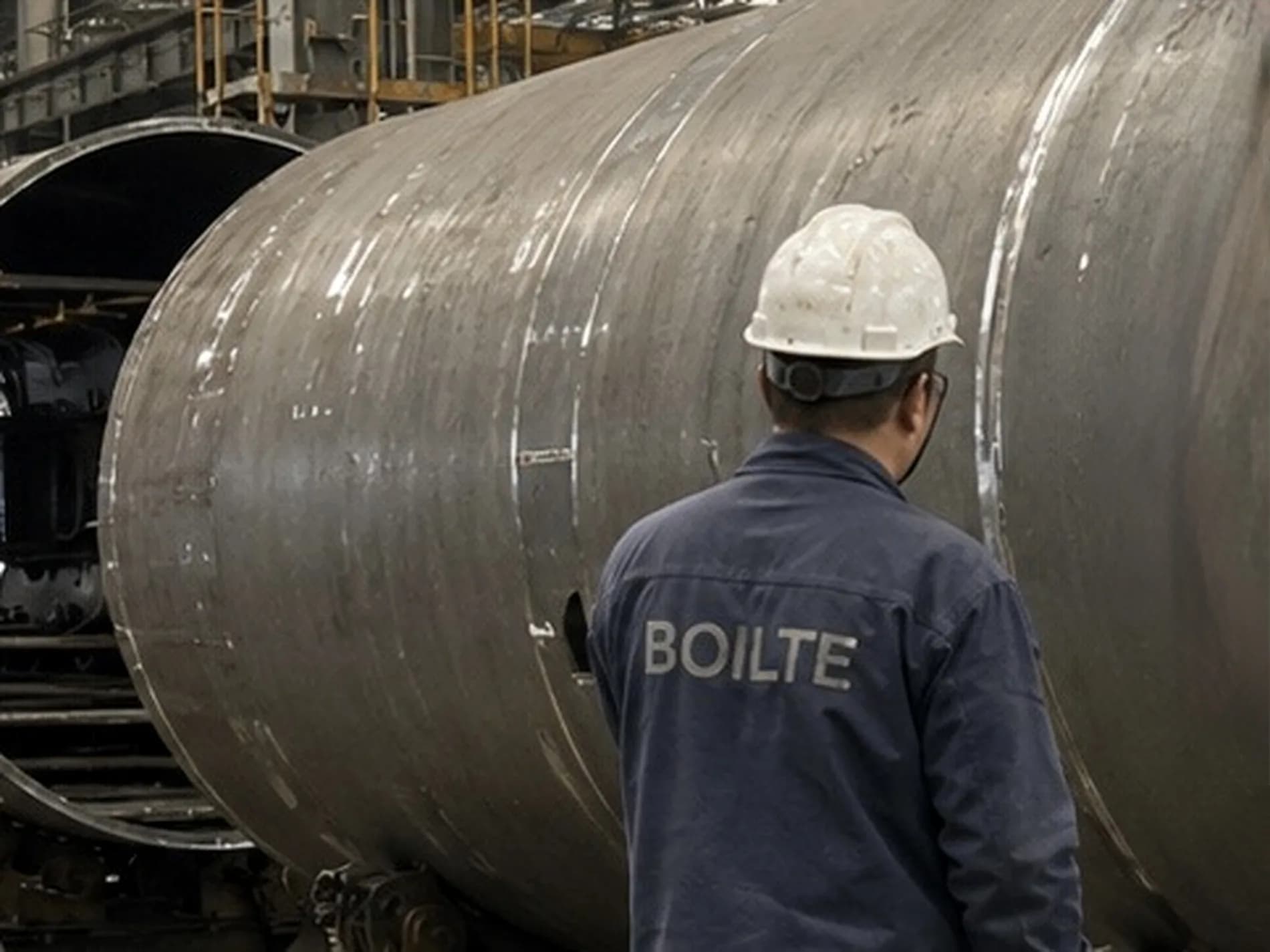
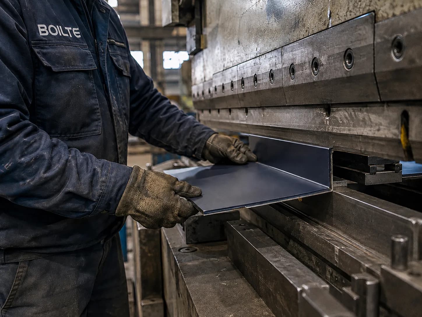

Metalworking, welding, assembly, painting shops, storage facilities, and test stands.
Current programme — 1000 boilers of any type and complexity per year.
CNC plasma, laser cutting, rolling, bending, automatic submerged arc welding, shot blasting chambers.
Designers, welders, non-destructive testing specialists, CNC operators, commissioning and service engineers.
Cutting of plate up to 80 mm thick with ±0.5 mm accuracy.
Precision cutting of thin sheet and complex contours.
Hydraulic plate-bending rollers for shells up to 4 m in diameter.
Automatic welding of longitudinal seams of boiler shells.
MIG/MAG welding for assembly seams and attached elements.
Surface preparation to Sa 2½ before painting.
Heat- and acid-resistant coatings with forced drying.
Hydraulic benches up to 40 bar, pneumatic up to 16 bar.
In choosing a boiler supplier you are really choosing a manufacturing site. It decides whether the shell is assembled to the geometry on the drawing, who actually welded the seams, how the quality was verified and how realistic the quoted date is. Boilte Manufacturing covers 22,000 m², holds 180 machine tools and employs 420 production staff. Design output is up to 1,000 boilers a year, and alongside that we keep the ability to build bespoke units of up to 60 MW.
Floor space guarantees nothing in itself; what matters is what occupies it. The site is laid out as an uninterrupted route for the product: metalworking shops, welding bays, assembly, painting, stores and test rigs all stand on one site and are linked into a single technological chain. A workpiece never leaves the premises between operations.
For you this is a question of accountability and lead time. When cutting, welding, painting and testing are carried out by different subcontractors, every handover costs days in logistics and blurs responsibility: an argument over who caused a deviation is usually settled at the customer's expense. Here a single organisation answers for the boiler, from the steel plate to the signed test report.
The quality of a boiler is set by the first operation. An error in cutting does not disappear; it turns into a weld gap that then has to be filled with deposited metal. Excess metal in the seam means greater heat input, higher residual stresses and a risk of distorting the shell. That is why we hold accuracy at the cutting stage instead of trimming parts to fit later.
The division between plasma and laser is not duplication but economics. There is no sense in cutting thick plate with a laser, and it is wasteful to put thin casing sheet full of holes through the plasma machine. The right operation delivers accuracy and cost efficiency together: nesting layouts are optimised, and less plate scrap means less steel in the price of the boiler.
After cutting, flat plate becomes a cylinder. Four plate-rolling machines form shells of up to 4 m in diameter, which covers the whole standard range and most bespoke projects. The quality of the rolling determines how evenly the edges meet for the longitudinal seam: the more accurate the geometry, the more consistent the penetration. Welding here is divided by purpose.
The ratio between the stations reflects the structure of the work: there are not many long critical seams, but they are the ones that determine the service life of the product, which is why they are given to automation. Pressure-bearing seams are made by qualified welders, and inspection is carried out by our own NDT technicians — not called in for the acceptance, but present in the process at all times.
A coating holds on the preparation, not on the paint. If mill scale and traces of corrosion are left on the surface, any coating will flake off during the first seasons, however much it cost. Three shot-blasting chambers prepare the surface to Sa 2½: the steel gains both cleanliness and the roughness needed for adhesion.
Two paint booths work with heat-resistant and acid-resistant coatings and are equipped with forced drying. Heat-resistant compounds are used near hot zones, acid-resistant ones where flue-gas condensate may form. Forced drying is not there for speed: it cures the coating under controlled conditions rather than at whatever humidity the shop happens to have.
No product leaves the factory untested. Five rigs mean tests are carried out without queuing and without any temptation to shorten the procedure for the sake of a dispatch plan: hydrostatic tests are run at up to 40 bar, pneumatic tests at up to 16 bar. The hydrostatic test confirms the strength and tightness of the pressure parts, the pneumatic test the tightness of the flue and air path.
The result is recorded in a report that forms part of the data book and is handed over to you with the boiler. You are welcome to witness the tests at our site in person or through your own technical inspection body. That is cheaper than finding a leak after installation: rectifying a defect in the shop takes hours, on site it takes weeks and the removal of pipework.
Machine tools do not run themselves. The structure of the production workforce reflects the full cycle: designers who develop the product and adapt it to your conditions; CNC operators who prepare the nesting layouts; welders qualified for specific types of joint; NDT technicians; commissioning and service engineers who travel to site.
Keeping the design office inside the factory solves a practical problem: a query on a drawing is closed in hours rather than weeks of correspondence, and a change you ask for during approval reaches the product without costing time. Commissioning engineers in the same loop know the construction of the boiler from the assembly stage, and experience from the field returns into the design.
The design output of the site is up to 1,000 boilers a year. Volume on that scale gives you what small-batch workshops cannot: settled operations with repeatable results and tooling costs spread across a series. At the same time, bespoke units of up to 60 MW pass through the same bays and the same test rigs. The lead time depends on how far the product departs from a proven design, so we quote it by type of order:
The range within each type is set by specific factors: how long drawing approval takes on your side, any non-standard items in the specification, the scope of works testing and the requirements for the documentation. We fix the date in the contract once those questions are closed, and from then on we work within it. If you need the equipment earlier, say so before signing.
AI consultant Boilte · Boilte · selection & sizing